Exemplary Info About Is Current Faster In A Parallel Circuit

How To Calculate Voltage In Parallel Circuit » Wiring Draw And Schematic
Current Speed in Parallel Circuits
1. What's the Buzz About Parallel Circuits?
So, you're curious about current speed in parallel circuits, huh? Well, you're not alone! It's a common question that pops up when people start diving into the world of electronics. Let's face it, electrical circuits can seem like a tangled mess of wires and confusing concepts. But fear not! We're going to break it down in a way that even your grandma could understand (assuming your grandma is into electrical engineering, of course).
First things first, let's get one thing straight: current isn't exactly "faster" in a parallel circuit in the way most people think. It's more about how the total current behaves and distributes itself throughout the circuit. Think of it like rush hour traffic. You've got multiple lanes (parallel paths) for the cars (electrons) to travel. Does that make each individual car go faster? Nope! But it does allow more cars to get to their destination at the same time, reducing congestion.
To understand why current acts the way it does in parallel circuits, we need to remember a fundamental principle: electrons are lazy. Okay, maybe not lazy in the "binge-watching Netflix all day" kind of way, but they do prefer the path of least resistance. In a parallel circuit, the current splits up and flows through all available paths. The path with the least resistance will naturally attract more current, while paths with higher resistance will see less current flow.
So, it's not that the current is speeding up, but rather that the total amount of current flowing through the circuit increases because there are multiple pathways for it to travel. It's like having multiple faucets filling a sink. Each faucet isn't necessarily flowing faster, but the sink fills up quicker because you've got more water coming in simultaneously. Make sense? I hope so, because there's more to come!

Measuring Current In A Parallel Circuit At Christie Owen Blog
Resistance is Futile... or is it?
2. Parallel Resistance
Let's talk resistance, baby! In a parallel circuit, the total resistance is lower than the resistance of any individual resistor. This might sound counterintuitive, but it's a crucial concept to grasp. Remember our traffic analogy? Adding more lanes (parallel resistors) reduces the overall congestion (resistance) for the cars (current) trying to get through.
The magic formula for calculating total resistance in a parallel circuit is a bit funky, but don't let it scare you. It goes something like this: 1/Rtotal = 1/R1 + 1/R2 + 1/R3 + ... and so on. Basically, you take the reciprocal of each resistor's resistance, add them all up, and then take the reciprocal of the result. This gives you the total resistance of the parallel combination.
A lower total resistance means that, for the same voltage, the overall current flowing through the circuit will be higher, as dictated by Ohm's Law (V = IR). That means for the same voltage applied to the entire circuit, since you have multiple paths for current to go down, it will increase total current in the circuit. This increase in current is why people often mistakenly perceive that current is "faster" in a parallel circuit. It's not about speed; it's about quantity!
And here's a fun fact: If you add more and more resistors in parallel, the total resistance gets smaller and smaller. Eventually, you could theoretically approach zero resistance, which would lead to a very large current draw. This is why it's important to use appropriate fuses and circuit breakers to protect your electrical circuits from overloading and causing a fire hazard. Safety first, kids!
The Voltage Vantage Point
3. Voltage
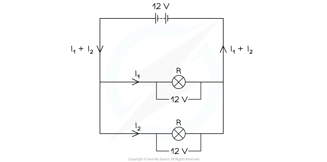
Here's a cool feature of parallel circuits: the voltage is the same across all components. Think of it like this: if you have multiple water slides side-by-side, the height of the starting point (voltage) is the same for all of them. Each water slide (resistor) might have a different shape or length (resistance), but the initial potential energy (voltage) is the same.
This consistent voltage is incredibly useful in many applications. For example, in your home's electrical wiring, appliances are connected in parallel. This ensures that each appliance receives the same voltage (typically 120V in North America) regardless of whether other appliances are switched on or off. Imagine if your TV got dimmer every time you turned on the microwave — that wouldn't be a very enjoyable viewing experience!
Because the voltage is constant across all branches of a parallel circuit, the current through each branch depends solely on the resistance of that branch. A branch with low resistance will draw a large current, while a branch with high resistance will draw a smaller current. This allows you to independently control the power delivered to different components in the circuit. It's like having individual volume controls for each speaker in a sound system.
So, while the total current in a parallel circuit might be higher than in a series circuit (for the same applied voltage), it's crucial to remember that the voltage remains constant across all components. This voltage consistency is a defining characteristic of parallel circuits and a key factor in their widespread use in electrical systems.

What Is A Parallel Circuit? Electricity
Parallel vs. Series
4. Understanding the Fundamental Differences
Let's have a quick recap. The difference between a parallel and a series circuit can be understood by its structure and function. In a series circuit, components are connected end-to-end, forming a single path for current flow. Imagine it as a single lane highway where all the cars (electrons) must travel in a single line. If one car stops, the whole line grinds to a halt. If one component fails, current stops flowing through the whole circuit.
In contrast, a parallel circuit offers multiple paths for current to travel. Components are connected side-by-side, creating multiple lanes on our highway analogy. If one lane is blocked, the cars can simply switch to another lane and continue their journey. If one component fails, current can still flow through the other branches of the circuit.
The total resistance in a series circuit is simply the sum of the individual resistances (Rtotal = R1 + R2 + R3 + ...). This means that adding more resistors in series increases the total resistance. In contrast, adding more resistors in parallel decreases the total resistance.
Voltage behaves differently in series and parallel circuits too. In a series circuit, the voltage is divided among the components. The voltage drop across each resistor is proportional to its resistance. In a parallel circuit, the voltage is the same across all components, as we discussed earlier.

Practical Applications and the Real World
5. Where do we find Parallel Circuits?
Parallel circuits are all around us, powering our homes, businesses, and even our cars. Think about the electrical wiring in your house. All the outlets and lights are connected in parallel. This allows you to turn on or off any device without affecting the others. If they were wired in series, turning off one light would plunge your entire house into darkness!
In automotive electrical systems, parallel circuits are used to power various components such as headlights, taillights, and the car's audio system. This allows each component to receive the correct voltage and operate independently.
Even complex electronic devices like computers rely heavily on parallel circuits. Microprocessors contain millions of transistors connected in parallel to perform various calculations and operations. The ability to create complex circuits with multiple parallel paths allows for highly efficient and versatile electronic devices.
Understanding parallel circuits is crucial for anyone working with electricity or electronics. Whether you're a seasoned engineer or just a curious hobbyist, grasping the principles of parallel circuits will help you design, troubleshoot, and repair electrical systems more effectively.
 Edexcel GCSE Physics")
FAQs
6. Q
A: No, not really. The speed of individual electrons doesn't dramatically increase. What changes is the total amount of current that can flow through the circuit because there are multiple pathways available. Think of it like adding more lanes to a highway; the cars aren't necessarily going faster, but more cars can get through simultaneously.
7. Q
A: Unlike a series circuit, if one branch of a parallel circuit is disconnected, the other branches will continue to function normally. This is because the current can still flow through the remaining paths. This is why your other lights stay on even if one burns out!
8. Q
A: It depends on the application! Parallel circuits are generally preferred for applications where you need to power multiple devices independently, such as in household wiring. Series circuits are more suitable for applications where you want to control the current flowing through all components simultaneously, such as in a string of Christmas lights (though modern Christmas lights often use parallel-series combinations).