Glory Tips About Should An Inductor Show Continuity

Inductor Basics For Beginners (Easy Guide, 2024)
Inductor Integrity
1. Understanding Inductor Testing
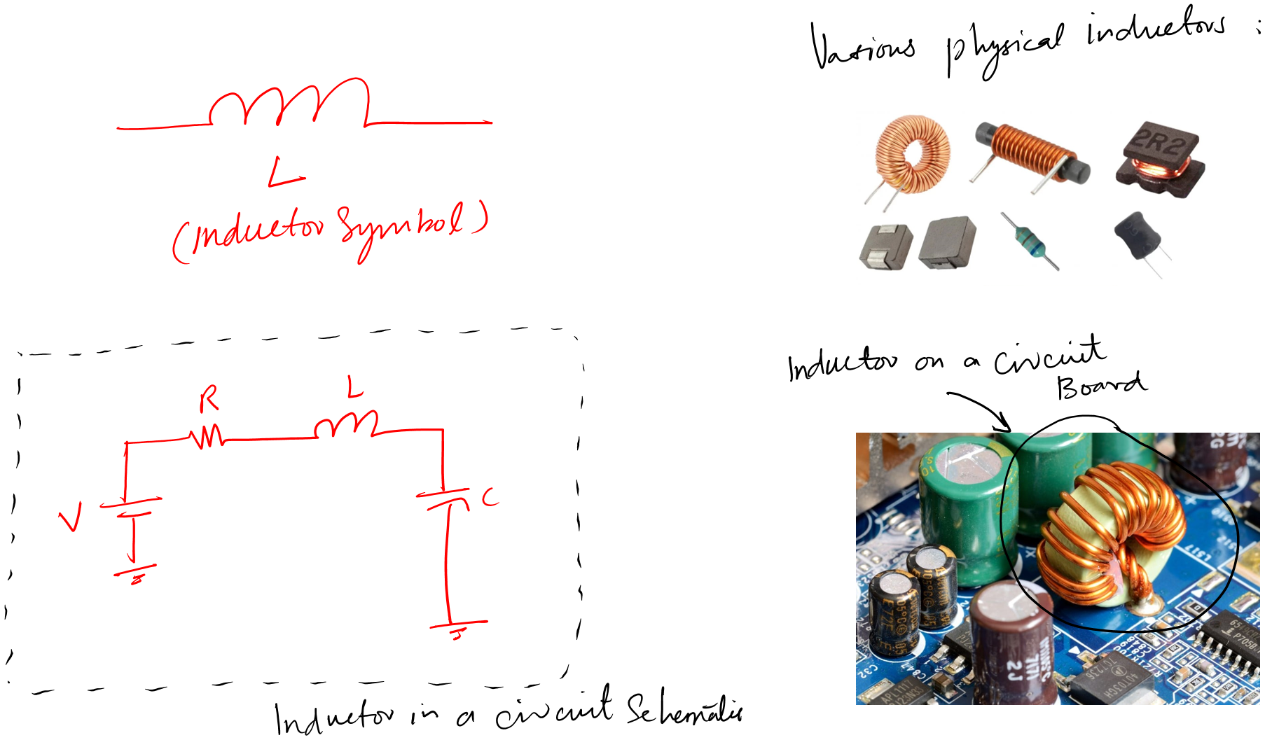
Alright, let's dive into the fascinating world of inductors and their ability to show continuity. Imagine an inductor as a tightly wound coil of wire, like a meticulously crafted slinky. Now, the question is: if you put a multimeter across its terminals and check for continuity, what should you expect? The answer, like many things in electronics, isn't a simple yes or no. It's more of a "it depends!" which is often the engineer's favorite phrase.
Think of it this way: if the inductor is perfectly fine and dandy, your multimeter should show continuity. After all, it's essentially a length of wire, right? But, and this is a big but, the resistance should be very low, ideally close to zero ohms. Your multimeter might beep to indicate continuity, but it should also display a low resistance value. If it shows an open circuit (infinite resistance), something is definitely amiss.
However, just because it doesn't show continuity doesn't always mean it's toast. Sometimes, the issue lies elsewhere in the circuit, masking the inductor's true state. So, before you pronounce a death sentence, make sure to isolate the inductor and test it independently. This is crucial in determining the actual component's state.
In a nutshell, a healthy inductor should exhibit continuity, represented by a very low resistance reading on your multimeter. Any deviation from this norm warrants further investigation. Think of it as a doctor checking your heartbeat — a steady beat is good, but an erratic one needs attention!

Advanced Electrical Principles Ppt Download
Deciphering the Resistance Reading
2. Defining Acceptable Resistance Levels
Okay, so we established that an inductor should ideally show low resistance when tested for continuity. But what exactly constitutes "low"? Is it like golf where the lower the score, the better, or is there a threshold we need to be aware of? Well, it depends on the inductor's specifications.
Every inductor has a datasheet, and it's your best friend when troubleshooting. This document will usually specify the inductor's DC resistance (DCR). DCR is the resistance of the wire used to create the coil. Its the value you should be aiming for when testing for continuity. If your multimeter reading is significantly higher than the DCR listed in the datasheet, Houston, we have a problem! It means the wire inside the inductor is likely damaged or partially broken.
For instance, if your inductor's datasheet states a DCR of 0.2 ohms and your multimeter reads 2 ohms, you've got a tenfold increase in resistance. This is a clear indication that something is wrong. Perhaps there's a partial break in the winding, or corrosion has crept in. Such issues usually degrade the inductor's performance and may cause the overall circuit to malfunction.
Don't have a datasheet? Fear not! As a general rule of thumb, smaller inductors (like those found in cell phones or small circuits) will have very low DCR, often less than 1 ohm. Larger inductors, especially those designed for high current applications, may have a DCR of several ohms. Use your judgment, and if in doubt, compare it to a known good inductor of similar specifications.

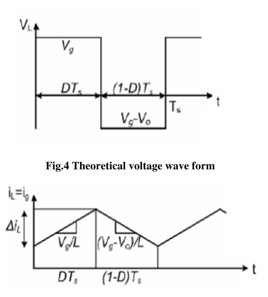
Through The Inductor Linearly Increases As Shown In Figure
When Continuity Fails
3. Troubleshooting Continuity Problems
Let's play detective and explore some of the usual suspects when an inductor fails to show proper continuity. Imagine the inductor as a tiny maze of wire; lots can go wrong inside those coils! A break in the wire is probably the most common issue. This could be a complete break or a partial one, both resulting in higher resistance than expected.
Another common culprit is corrosion. Over time, especially in humid environments, corrosion can creep into the inductor's windings, increasing resistance and eventually leading to failure. You might see visible signs of corrosion on the inductor itself, like green or white powdery residue. If so, its time to replace it.
Sometimes, the inductor isn't actually faulty. The problem could lie in the surrounding circuit. A short circuit in another component connected to the inductor could give the impression of an open circuit when you are testing for continuity across the inductor. Therefore, it's essential to isolate the inductor before testing to get an accurate reading.
Finally, always double-check your test equipment. A faulty multimeter or poor connections can give false readings. Make sure your multimeter is calibrated correctly and that your test leads are in good condition. Clean the contacts on the inductor and your test leads to ensure a good connection. A little preparation can save you a lot of unnecessary troubleshooting!

Inductor SteadyState And Transient Analysis YouTube
Testing Beyond Continuity
4. Going Beyond the Basic Test
While continuity testing is a good starting point, it's not the be-all and end-all of inductor evaluation. Think of it like a basic medical check-up; it gives you a snapshot, but you might need more specialized tests for a complete diagnosis. There are other parameters that can tell you more about an inductor's health, such as inductance and quality factor (Q).
Inductance, measured in Henrys (H), is the inductor's ability to store energy in a magnetic field. If the inductance is significantly lower than the specified value, it could indicate that the core material has been damaged, or the winding has shorted turns. A dedicated LCR meter is required to measure inductance accurately. These meters send a signal to the inductor and calculate the inductance and capacitance.
The quality factor (Q) measures the inductor's efficiency. A high Q indicates that the inductor is storing energy effectively, while a low Q suggests energy losses. A low Q can be caused by high resistance in the winding or core losses. Like inductance, Q is measured with an LCR meter. A decrease in Q usually goes together with a decrease in inductance.
In addition to these electrical measurements, visual inspection is crucial. Look for any signs of physical damage, such as cracks in the core, broken windings, or discoloration. A burnt smell is also a dead giveaway! Remember, a healthy inductor is not just electrically sound; it's also physically intact. Consider this a preventative test for problems.

Inductors in Action
5. Practical Applications and Maintenance
Now that we've covered the theory, let's bring it all together with some real-world scenarios. Think about an inductor in a power supply. It's crucial for filtering out unwanted noise and providing a stable voltage. If the inductor fails, the power supply might produce unstable output voltage, potentially damaging sensitive electronic components.
Consider an inductor in a radio frequency (RF) circuit. It's part of the tuning circuit, determining the frequency the radio can receive. If the inductor's inductance changes due to damage, the radio will no longer be able to tune to the desired frequency. This can result in weak signals or even complete failure.
To keep your inductors in tip-top shape, consider a few best practices. Avoid exposing them to excessive heat or humidity. Store them in a dry environment to prevent corrosion. When soldering, avoid overheating the inductor. Excessive heat can damage the insulation on the winding, causing short circuits. Always use proper ESD protection when handling inductors, especially small surface-mount components.
And finally, when in doubt, replace it! Inductors are relatively inexpensive, and replacing a suspect inductor can save you a lot of headaches down the road. Think of it as preventative maintenance; a small investment that can prevent larger problems later. A solid strategy is to keep a small stock of common inductors that are used in your projects.

Frequently Asked Questions (FAQs)
6. Quick Answers to Common Queries
Let's tackle some common questions about inductor continuity testing.
Q: My multimeter shows a very low resistance, almost zero ohms. Is my inductor shorted?
A: Not necessarily. A healthy inductor should have a very low DCR. Check the datasheet. If the DCR matches your reading, the inductor is likely fine. However, if the resistance is exactly zero, double-check for shorts in the surrounding circuit.
Q: I tested my inductor in-circuit, and it shows an open circuit. Does this mean it's faulty?
A: Not necessarily. Other components in the circuit could be affecting the reading. Remove the inductor from the circuit and test it independently to get an accurate measurement. A capacitor in series with the inductor can cause an open circuit.
Q: Can I test an inductor with just a multimeter, or do I need special equipment?
A: A multimeter can be used to check for continuity and estimate the resistance. However, for more comprehensive testing, such as measuring inductance and Q factor, an LCR meter is required.